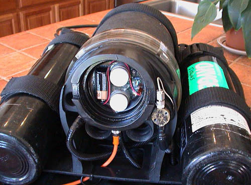
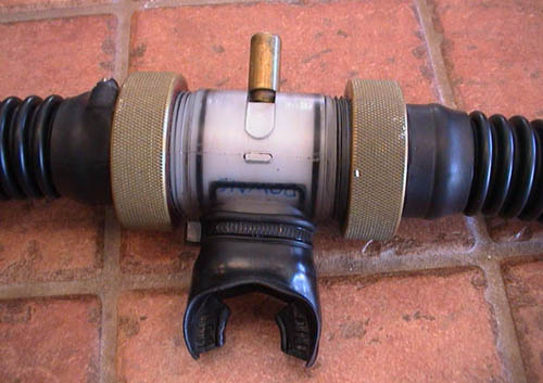
Top view:
Head cap and breathing hoses removed (note the standard 9v battery)
Close-up
of electronics with all caps removed:
The
top chamber houses the setpoint selector and calibration button for the digital electronics, and the bottom chamber houses
the trim pots for the analog secondary. The O2 solenoid is located to the right of the main chamber, and on the outside of
the breathing loop.
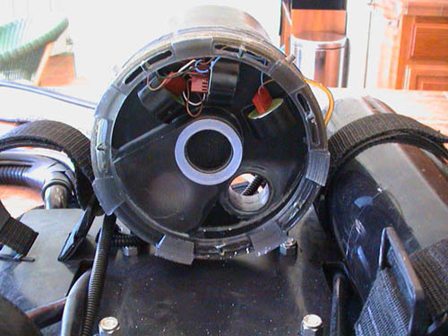
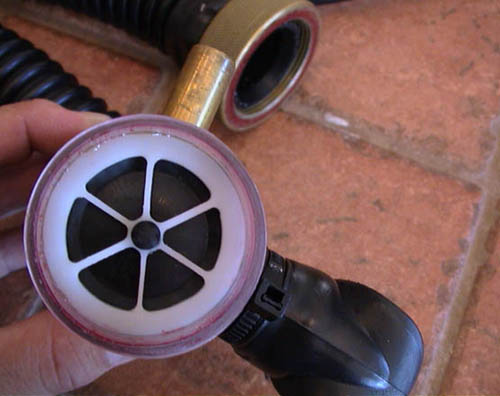
Bottom view of head:
The sensors are on top, and the depth transducer is under the #2 sensor
connector. O2 is injected into the exhaled gas plenum (lower left region) before
the CO2 rich gas enters the scrubber through the center bore. Also, a ¼ foam pad (not shown) covers
the entire assembly except for the center bore when assembled. The chamfered tabs around the perimeter are scrubber alignment
guides.
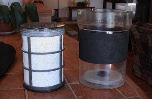
Scrubber (packed w/ 8-12)
and bucket:
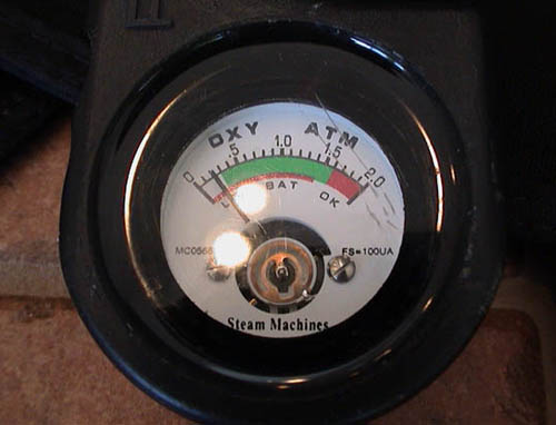
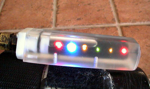
Secondary Display:
It gives analog readings of each sensor's output, battery charge, and setpoint selection.
Primary display:
LEDs indicate PO2 status and alarm situations
Legend (from left to right):
battery/sensor alarm (bi-color LED lit green to indicate sensor issue), > PO2 .2 below setpoint (blue),
>.1 low, PO2 at setpoint (green), >.1 high, >PO2 .2 above setpoint (red)
Mouthpiece:
Red marks the inhale (O2 rich) side, and blue marks the exhale (O2 lean) side
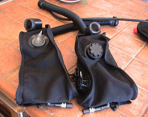
Counter-lungs:
The one on the left is the inhale lung with the ADV. The one on the right is the exhale lung with dump
valve and O2 bypass. The devices at the base of each lung
are locking drains.
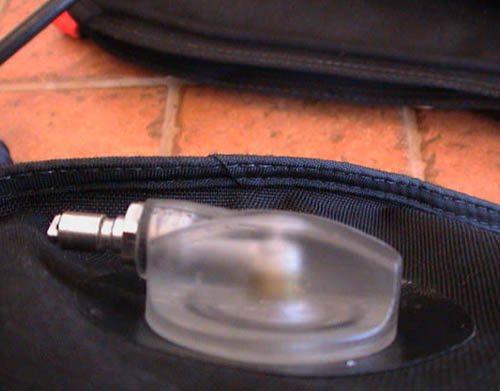
ADV:
It contains a Schrader valve that is actuated
by complete lung collapse.